Chicken Door Repairs
Carole, our oldest and largest chicken, is not exactly graceful. When getting off the top perch, she frantically flaps her wings while launching herself at the exit door. Unfortunately, that's exactly where the the electronics which control our automatic chicken door are mounted. This week, the circuit board just couldn't take any more. This integrated circuit had two of its pins severed as a result of the last impact:
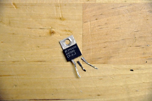
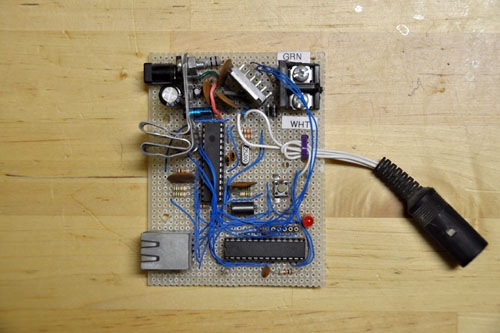
This chip was part of the power circuit for the board, so the damage made the whole thing stop working. I found a replacement part and reassembled the circuit board:
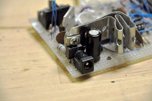
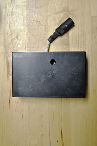
Our electronics enthusiast readers out there will notice that the controller is built on perfboard and hand-assembled (it's all point-to-point soldered). This means that the whole thing is a bit more fragile than one that's assembled on a custom-etched board. To avoid further avian entanglements, I went out and found an enclosure for it:
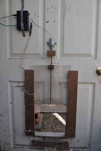
Here's what the whole thing looks like after the defenses have been fortified and the controller reinstalled in the shed:
Many readers have asked for more information about the chicken door, so the rest of this post dives into some more detail about the controller, mechanics, and lessons learned after living with the design for several years.
The circuit employs an 8-bit AVR microcontroller from Atmel and a single-chip ethernet controller from Microchip. While I didn't build this from any given set of plans, the most similar project out there is a design by Guido Socher at tuxgraphics.org. (For those of you getting started with microntrollers, I heartily recommend Guido's site -- wonderful tutorials, good explanations, and really nice kits if you'd like to go that direction. I ended up purchasing some of his circuit boards and am in the process of replacing some of my hand-wired designs with them.) In addition to the cpu and network chip, the board has an H-bridge which is used to control a small DC motor.
- an NTP client which checks in once per hour with the NTP service on our local network in order to have an accurate time-of-day
- a single-threaded web server (which displays system status and responds to simple GET requests to manually trigger door up/down or NTP resync)
- detecting and debouncing the state of the pushbutton switch on the board and the off-board limit sensors
- triggering the daily schedule of door up and down (I calculated the time of civil twilight for every day of the year at our position on earth and put this into a table)
The software has been reasonably robust. In the several years it has been running, there has only been one software-related lockup. (I originally had written a bug in the NTP client code such that the program got stuck in an infinite loop.)
On the hardware side, however, I did have a bunch of lockups early on. These were due to voltage regulation issues (I started out with a power supply that didn't deliver enough current to both drive the electronics and the motor) and motor-related voltage/current spikes (which got solved by adding a big capacitor to smooth the input to the voltage regulator IC and some diodes to limit the effects of the transients).
After addressing the various hardware and software bugs, the electronics have been relatively maintenance-free, modulo bird strikes.
The mechanics of the door are a simple design, in concept. A motor drives a screw, along which travels a captive nut. The nut is attached to the door. Running the motor in one direction makes the door go up, while the other makes it go down. There are limit switches which detect when the door is at each end of travel so the cpu knows when to stop running the motor.
However, compared to the electronics, the door mechanics have required constant care and feeding.
Here's the setup which raises and lowers the door:
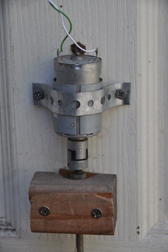
From the top down, there is a motor, a two-part linear bushing, and a long rod passing through a circular ball bearing (obscured by a piece of wood which is holding said ball bearing in place against the door).
The linear bushing allows the motor's full torque to be transmitted to the threaded rod. Without it, it is very difficult to have the motor turn the screw without binding. This is because it's almost impossible to align the motor's drive shaft to be exactly colinear with the threaded rod. The bushing allows the motor and rod to be slightly misaligned (the two metal ends of the bushing connect to motor and rod respectively, and the two are held together with a rubber piece in the middle which allows the ends to wiggle and flex).
The housing of ball bearing is clamped in place against the door. Even though the housing is immobile, there's a center piece to the bearing which spins freely. The threaded rod passes through this center piece and is clamped to it (one nut cinched on each side).
My complaint about all of these parts is that alignment is difficult. The motor wants to spin around, but binds if clamped tightly to the door. Instead, I've loosely clamped it to the door and prevent it from spinning in place by driving a screw near the top and having the screw catch a small flange in the motor's casing.
The linear bushing works its way loose on a regular basis. There are small captive screws which clamp the bushing to the motor shaft; those screws get loose and need to be tightened every few months.
The ball bearing claims not to need lubrication, but I have not found that to be the case. All of the dust kicked up by the chickens ends up working its way into the bearing. This requires me to add a blob of molybdenum grease to the bearing twice per year.
The threaded rod itself also likes to collect dust, wood shavings, and feathers. I need to lubricate the rod with silicone lubricant every few months or the whole thing will get stuck on the captive nut attached to the door mechanism.
Here's a photo of the limit sensors:
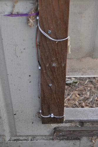
The limit sensors are reed switches. They're fully enclosed in plastic (because they respond to the presence of a magnet), so are unaffected by the dust and such in the chicken shed. Of all parts of the hardware, these are the only bits that haven't given me any trouble.
posted by noel on 06/23/12